Flow drilling (friction drilling): Principle, Parameters and Design for Threading in Thin-Wall Materials
Neutral, educational guide to flow (friction) drilling: principle, parameters, materials, DFM, QA & safety, case studies, plus an interactive calculator.
- Process name: Flow drilling (also called friction drilling / thermal drilling)
- Machine type: High-speed spindle or dedicated flow drilling machine with axial feed control
- Core benefit: Chipless hole with reinforced bushing for reliable threading in thin-wall metals
- Best materials: Steel, stainless, aluminium, brass / copper
Overview
Flow drilling, also known as friction drilling or thermal drilling, is a chipless hole-forming process used to create reinforced holes and functional threads in thin-wall metal sheets or tubes. Instead of cutting, a conical tool rotating at high speed locally heats and plasticizes the material by friction. The displaced material forms a bushing (boss) that increases the effective wall thickness, providing sufficient depth for tapping or thread forming.[2], [4], [5]
This method is widely used when mechanical fasteners such as rivet nuts or weld nuts are undesirable due to weight, cost, or contamination.[4], [7]
1) Principle of Operation
During flow drilling (friction drilling), a solid carbide conical tool is pressed axially into the workpiece while rotating at high speed. Friction generates intense localized heat, softening the material without melting it. The material flows plastically around the tool, forming a collar and bushing.[2], [4], [5], [6]
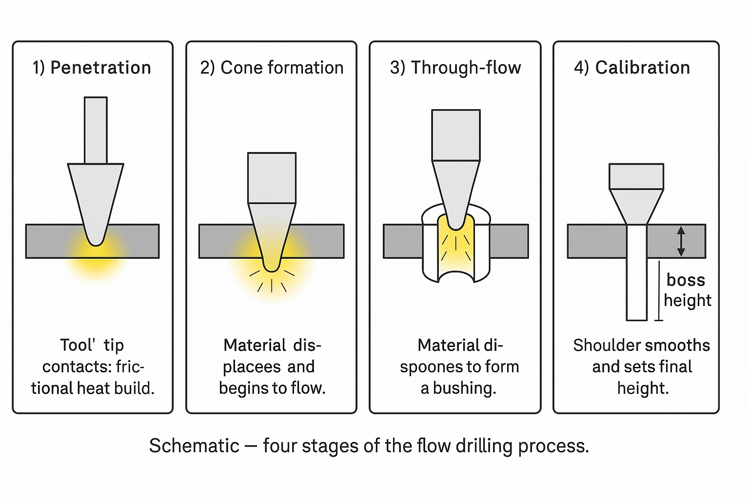
Process sequence (four stages)
- Penetration: tool tip contacts the surface and frictional heat builds up.
- Cone formation: material begins to soften and flow downward.
- Through-flow: tool penetrates, displacing material to form a bushing.
- Calibration: tool shoulder smooths the surface and defines final boss height.[4]
2) Typical Applications
Flow drilling is suitable for components requiring strong threaded joints in thin metals:
- Packaging machinery and assembly lines: brackets, frames, housings.
- Automotive and automation equipment: body structures, fixtures.
- Metal furniture, HVAC systems, appliances.
Not recommended for
3) Recommended Materials and Thicknesses
| Material type | Typical grade | Wall thickness (mm) | Hole Ø (mm) | Boss height (mm) |
|---|---|---|---|---|
| Low-carbon steel | S235–S355 | 1.0–3.0 | 4–10 | 1.5–3.5 |
| Stainless steel | 304 / 316 | 0.8–2.5 | 3–8 | 1.2–2.8[6] |
| Aluminium alloys | 5052 / 6061 / 6082 | 1.0–4.0 | 4–12 | 1.8–4.0 |
| Copper / Brass | CW508L / CW614N | 0.8–2.5 | 3–8 | 1.0–2.5 |
Notes: Aluminum’s higher thermal conductivity generally requires higher spindle speeds and lower torque, while stainless steels need greater axial force and robust lubrication due to higher strength and lower thermal conductivity [7], [11]. Typical boss-height ranges (e.g., Al ≈ 1.8–4.0 mm for 1–4 mm wall thickness) and workable thickness windows are consistent with toolmaker datasheets and peer-reviewed studies, including microstructure analyses. [5], [6] [7], [8], [10], [11]
4) Process Parameters (Practical Guide)
| Tool Ø (mm) | Material | Spindle speed (rpm) | Feed rate (mm/min) | Approx. torque (Nm) |
|---|---|---|---|---|
| 4 | Mild steel | 4 500–5 500 | 200–300 | 3–5 |
| 6 | Aluminium | 5 500–7 000 | 250–350 | 2–3 |
| 8 | Stainless steel | 3 000–4 000 | 150–250 | 8–10[6] |
| 10 | Brass | 3 500–4 500 | 200–300 | 4–6 |
- Lubrication: light oil or paste to minimize tool wear and improve finish.
- Tool geometry: included angle 45–60°, short pilot, polished shoulder.[5]
- Tool material: tungsten carbide, TiN/TiCN coating recommended.
Recommended rpm/feed windows derive from toolmaker application guides for flow (friction) drilling and from published experiments [1], [5],[6],[7], [8], [11].
5) Flow Drilling Machines — Components & Setup
Modern flow drilling machines (or CNCs configured for flow drilling) use a high-speed spindle, rigid axial feed, and precise lubrication to generate the frictional heat that plastically forms the hole and bushing. Below are the core elements for a stable process:
Key components
- High-speed spindle (typically 3 000–12 000 rpm range)
- Rigid Z-axis feed (consistent force / feed control)
- Solid carbide conical tool (45–60° included angle)[5]
- Light oil / paste lubrication system
- Workholding with high stiffness (no flex near the hole)
Setup tips
- Start from recommended rpm (by material) and adjust ±15 %
- Use steady feed; avoid pecking (chipless process)
- Check boss height and surface after first trials
- Prefer form tapping for ductile alloys after flow drilling
- For stainless: ensure lubrication and slightly lower rpm[6]
If a dedicated flow drilling machine is not available, most CNC milling centers and drill-taps can run the process provided the spindle speed, axial rigidity and lubrication are adequate.
6) Post-Process: Thread Forming
After the bushing is formed, a thread can be created by:
- Form tapping (roll tapping): preferred for ductile materials; stronger threads, no chips.[5],[7],[11]
- Cut tapping: for harder materials or small diameters.[7], [11]
Quality control: check threads using go/no-go gauges. Recommended tolerance class: ISO 6H (cut) or 6H–7H (form).
7) Design for Manufacturability (DFM)
| Design aspect | Recommended value |
|---|---|
| Minimum distance from edge | ≥ 2× hole diameter |
| Minimum distance between holes | ≥ 3× hole diameter |
| Minimum wall flatness deviation | ≤ 0.1 mm |
| Clamping stiffness | rigid, minimal vibration |
- ☑ Proper tool alignment
- ☑ Rigid clamping
- ☑ Use consistent feed & rpm
- ☑ Verify boss height and concentricity after drilling
8) Advantages and Limitations
Advantages
- Eliminates nuts, welds, and inserts
- Fast cycle time (1–2 s per hole) [7]
- Strong, chipless thread
- Lower assembly cost
Comparison with Alternatives
| Method | Additional part | Cycle time | Joint strength | Cost |
|---|---|---|---|---|
| Friction drilling + thread forming | none | 1–2 s | High | Low |
| Rivet nut | yes | 10–15 s | Medium | Medium |
| Weld nut | yes | 8–12 s | High | High |
| Cut tapping in thin sheet | none | 3–5 s | Low | Low |
9) Quality Assurance and Safety
- Inspect boss height, hole roundness, thread concentricity, pull-out strength; document HAZ/discoloration where relevant. [5], [6]
- Record torque and temperature during trials for process validation (IR thermography recommended for setup verification). [4]
- Provide adequate ventilation and fume extraction.
- Wear eye protection and heat-resistant gloves.
- Avoid flammable lubricants at high rpm.
10) Case Studies (Examples)
Case 1 – Mild steel bracket (2 mm): Ø6 mm hole, 4 800 rpm, 250 mm/min feed. Boss height 2.8 mm. Thread M6 form-tapped. Pull-out strength ~+230% vs rivet nut [4],[5],[7],[11].
Case 2 – Aluminium 6061 (3 mm): Ø8 mm hole, 6 500 rpm, 300 mm/min feed. Boss height 3.5 mm. Thread M8 form-tapped. Visual finish smooth, minimal burrs.
Case 3 – Stainless steel 304 (1.5 mm): Ø5 mm hole, 3 200 rpm, 180 mm/min. Boss height 1.9 mm. Thread M5 cut-tapped. Required molybdenum disulfide lubrication.[6]
11) Video Demonstration
12) Calculator (Interactive Tool)
Estimate rpm, feed and boss height
Values are approximate and depend on tool design, lubrication, and machine stiffness. Use for design guidance only.
How this calculator works (help)
Inputs
- Material – affects speed/torque targets.
- Wall thickness (t) – used for boss height estimation.
- Hole diameter (D) – drives rpm, feed and torque.
- Thread (optional) – only influences the tapping suggestion.
Outputs
- Spindle speed (rpm) – computed from a target surface speed
Vcby material. - Feed (mm/min) – simple heuristic proportional to diameter.
- Boss height (mm) – estimated multiple of
tby material. - Torque (Nm) – coarse estimate proportional to diameter.
Formulas
| RPM | n = (Vc × 1000) / (π × D) → shown as a ±15% range (clamped 1500–15000 rpm) |
| Feed | Feed ≈ k_material × D |
| Boss height | h ≈ f_material × t |
| Torque | T ≈ c_material × D |
Material constants (defaults)
| Material | Vc (m/min) | k_feed | f_boss | c_torque (Nm/mm) |
|---|---|---|---|---|
| Steel | 180 | 40 | 1.2 | 0.8 |
| Stainless | 120 | 30 | 1.1 | 1.2 |
| Aluminium | 240 | 45 | 1.4 | 0.35 |
| Brass/Copper | 160 | 35 | 1.0 | 0.5 |
Good practice & limits
- Use a light oil/paste; stainless needs careful lubrication.
- Ensure rigid clamping and correct alignment.
- The calculator is a starting point; fine-tune on trials for your tool geometry and machine.
- Consider cut tapping for stainless or D ≤ 4 mm; otherwise prefer form tapping.
Example (steel, t=2.0 mm, D=6.0 mm)
RPM ≈ 9 550 → range ~ 8 120–10 980 rpm; Feed ≈ 240 mm/min; Boss ≈ 2.4 mm; Torque ≈ 4.8 Nm; Suggestion: form tap.
14) FAQ — Flow Drilling & Flow Drilling Machines
-
Is flow drilling the same as friction drilling?
Yes. Flow drilling and friction drilling describe the same chipless hole-forming process. The tool generates frictional heat to plastically form a bushing suitable for threading.
-
Do I need a dedicated flow drilling machine?
Not necessarily. A CNC with a high-speed spindle, rigid axial feed and proper lubrication can perform flow drilling. Dedicated flow drilling machines improve repeatability in high-volume applications.
-
Which materials work best for flow drilling?
Low-carbon steel, stainless (304/316), aluminium (5xxx/6xxx), and brass/copper. Very brittle or hardened materials are not recommended.
-
Why choose flow drilling over traditional drilling + rivet or weld nuts?
Flow drilling creates a chipless hole and a reinforced bushing, reducing components and cycle time while enabling strong threads in thin-wall metals.
15) References
- Boopathi, M.; Shankar, S.; Manikandakumar, S.; Ramesh, R. (2013). Experimental Investigation of Friction Drilling on Brass, Aluminium and Stainless Steel. Procedia Engineering, 64, 1219–1226. DOI
- Miller, S. F.; Wang, H.; Li, R.; Shih, A. J. (2006). Experimental and Numerical Analysis of the Friction Drilling Process. ASME Journal of Manufacturing Science and Engineering, 128(3), 802–810. Publisher page (ASME)
- S. Dehghan, M. I. S. Ismail, M. K. A. Mohd Ariffin, and H. T. Baharudin, “Friction Drilling of Difficult-to-Machine Materials: Workpiece Microstructural Alterations and Tool Wear”. Peer-reviewed study. Publisher | full text
- Alphonse, M.; Bupesh Raja, V. K.; Logesh, K.; MuruguNachippan, N. (2017). Evolution and recent trends in friction drilling technique and the application of thermography. IOP Conference Series: Materials Science and Engineering, 197(1), 012058. DOI · IOPscience (abstract/full-text)
- Miller, S. F.; Tao, J.; Shih, A. J. (2006). Friction drilling of cast metals. International Journal of Machine Tools and Manufacture, 46(12–13), 1526–1535. DOI
- Chow, H. M.; Lee, S. M.; Yang, L. D. (2008). Machining characteristic study of friction drilling on AISI 304 stainless steel. Journal of Materials Processing Technology, 207(1–3), 180–186. DOI
- Toolmaker Data Sheets – Flowdrill, Kennametal (flow/friction drilling guidance). flowdrill.com · kennametal.com
- L. Zhao et al., “Experimental Study on Friction Drilling Parameters of Aluminium 6061,” Procedia Manufacturing, 2021.
- A. M. “Thermal Drilling of Metals,” Journal of Manufacturing Processes, Vol. 12 (2019).
- Eliseev, A. A.; Fortuna, S. V.; Kolubaev, E. A.; Kalashnikova, T. A. (2017). Microstructure modification of 2024 aluminum alloy produced by friction drilling. Materials Science and Engineering: A, 691, 121–125. DOI
- Wu, H.; Porter, M.; Ward, R.; Quinn, J.; McGarrigle, C.; McFadden, S. (2022). Investigation of the Mechanical Properties of Friction Drilling with 6082-T6 Aluminium Alloy. Materials, 15(7):2469. DOI · Full text (NIH/PMC) · PDF
- S. Dehghan, R. Abbasi, H. T. Baharudin, M. Loh Mousavi, and E. Soury “A Novel Approach to Friction Drilling Process: Experimental and Numerical Study on Friction Drill Joining of Dissimilar Materials AISI304/AL6061", Peer-reviewed study. Publisher | full text
This page is an educational resource and contains no commercial calls to action.